
The ConsolesActuator ConsoleUse the console
Use the Actuator Console
Command motion, tune and save drive settings, and inspect or record telemetry with the Actuator Console.
Use this page after First move to choose a motion tool, tune the actuator and inspect its response. Each task below includes the controls to use and what to check afterwards. The pictures show the current Console with a simulated M actuator; IDs and firmware versions are examples.
Find your way around
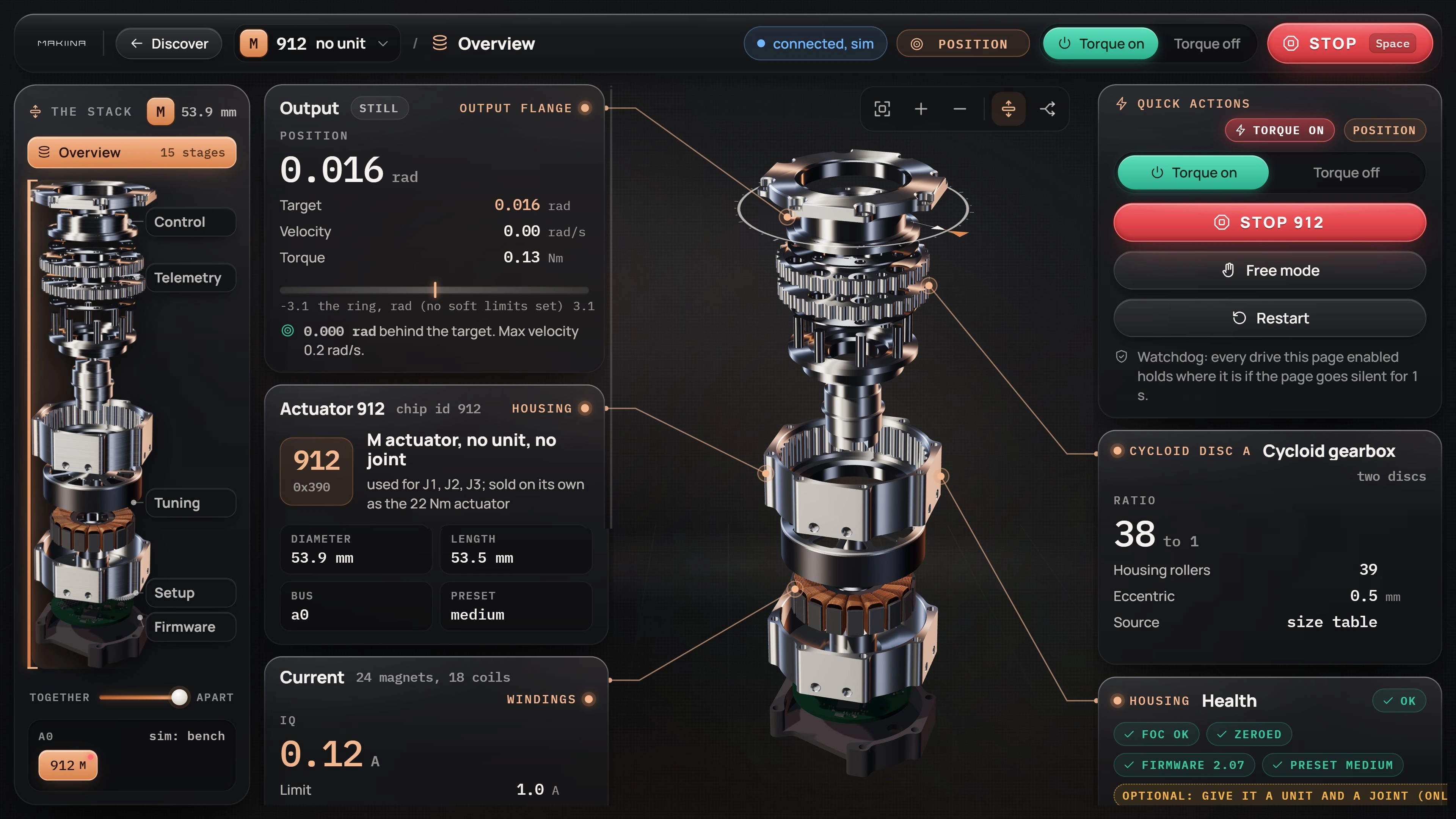
The top bar names the selected actuator and shows the connection, mode, Torque on, Torque off and STOP. Use the actuator selector or a board in the left bus list to change the selection. Read its ID before sending a command or writing a setting.
The left navigation follows the parts in the exploded model. Point at a part to name it; click it to open the related page. The tools above the model fit, zoom, take it apart or show a section through it.
| Page | Use it to |
|---|---|
| Discover | Find adapters and boards, check their health and rescan. |
| Overview | Inspect the selected actuator's output, motor, board and identity. |
| Control | Set limits and command motion. |
| Tuning | Read drive settings, write changes, test a step and save a profile. |
| Telemetry | Plot live measurements and save CSV data. |
| Firmware | Compare versions, update one board and read its boot report. |
| Setup | Change stored identity, zero, direction, preset or termination. |
Firmware and Setup change how the board starts and identifies itself. Their steps are in Actuator maintenance.
Command motion
Open Control, check the actuator ID and set the current and speed limits for your mechanism. Press Torque on before commanding motion. Start with Position mode and a small travel, as in First move.
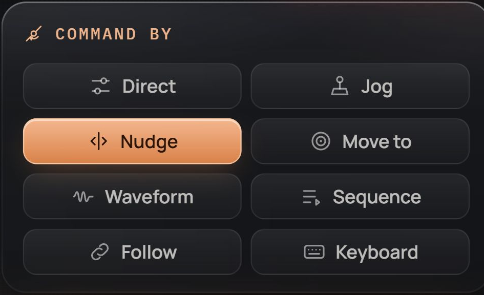
Drive mode chooses what the target means. Command by chooses how you supply that target. Changing the mode and choosing a waveform are different operations.
| Drive mode | Target | What happens |
|---|---|---|
| Position | rad at the output | Move to an angle and hold it. |
| Velocity | rad/s at the output | Keep turning at the requested speed; the sign chooses direction. |
| Current | A | Apply torque-producing motor current. This does not hold a chosen angle. |
| Torque | N m | Apply a torque using the drive's configured torque model. |
| Free | none | Release the motor for movement by hand. Support a load first. |
Move to an angle or jog by hand
- Direct: type Target and press Send. Dragging its slider sends targets continuously. Target = measured sets the target to the current measured position.
- Jog: set Button speed, then hold a direction button or drag the stick. Release to stop. A lost release expires after 0.4 s.
- Nudge: press one signed step button. Each click makes one short move relative to the starting position.
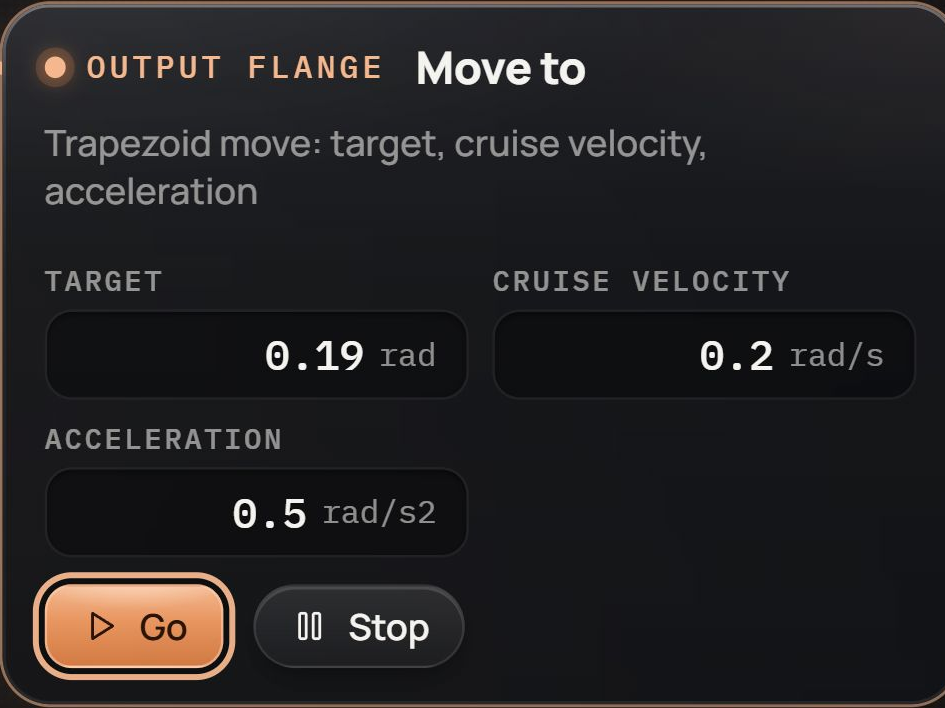
- Move to: enter Target, Cruise velocity and Acceleration, then press Go. The output accelerates, cruises if there is enough distance, and slows into the target. Stop ends that move and holds.
- Keyboard: select it and use the left or right arrow while held. Check its instructions and focus before using the keys.
For a first Move to test, choose a target 0.05 rad from the measured position, a cruise velocity of 0.2 rad/s and acceleration of 0.5 rad/s². Check that the target lies within your mechanism's free travel. The move still respects the Console's speed and position limits.
Repeat a controlled motion
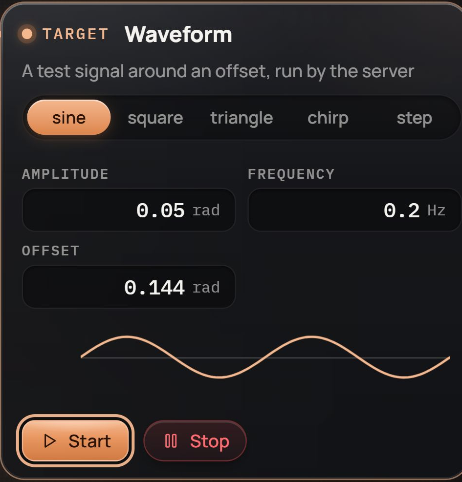
In Position, choose Waveform. Set Offset to the current measured output angle, Amplitude to 0.05 rad and Frequency to 0.2 Hz. Select sine, then Start. One cycle takes five seconds and stays within 0.05 rad on either side of the offset. Press Stop to finish and hold.
The other shapes are square, triangle, chirp and step. A square or step changes the target abruptly; the measured output still responds through the drive and its limits. A chirp varies frequency to explore the response. Watch the Response chart and use small amplitudes while tuning.
For distinct destinations, choose Sequence, enter each target and dwell time, set the move velocity and acceleration, choose whether to loop, then Run. Check every waypoint against the free travel.
With two actuators, Follow uses another actuator as the leader. Select it, set scale and offset, then Follow. The follower target is the leader's measured position times the scale, plus the offset. A negative scale reverses direction. Check the resulting target before starting; an offset can make the follower move immediately.
Check the torque model
In Torque mode, read the torque model shown on Control before sending a target. The firmware's default constants do not necessarily describe the output gearbox. Use output torque writes the selected size's motor constant and ratio so targets represent output torque; these settings remain only until the board restarts unless you save and reapply them.
Displayed torque is an estimate from motor current and gearing, not a measurement from an output torque sensor. Gear losses and friction affect the torque the mechanism actually receives.
Tune and save settings
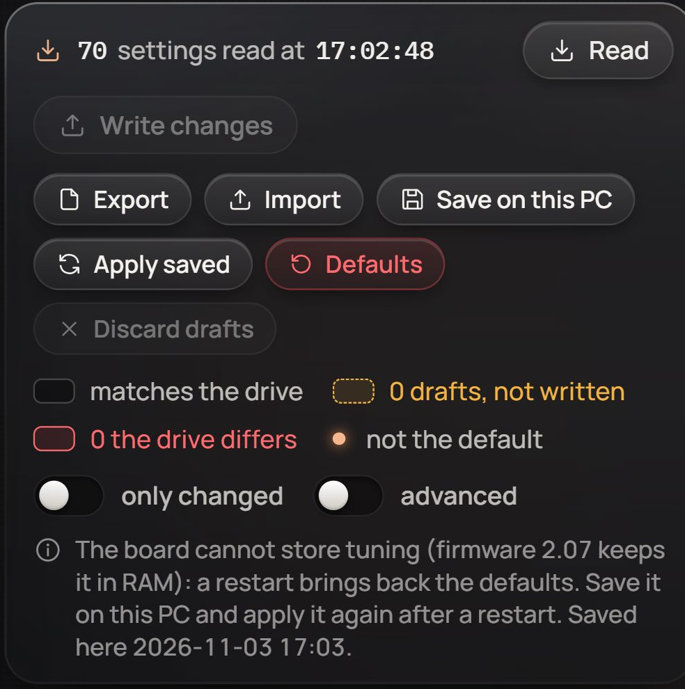
Open Tuning and press Read. The settings are grouped by the loop or component they affect. Hover over a setting, or focus it with Tab, to read its meaning, range, default and storage behavior.
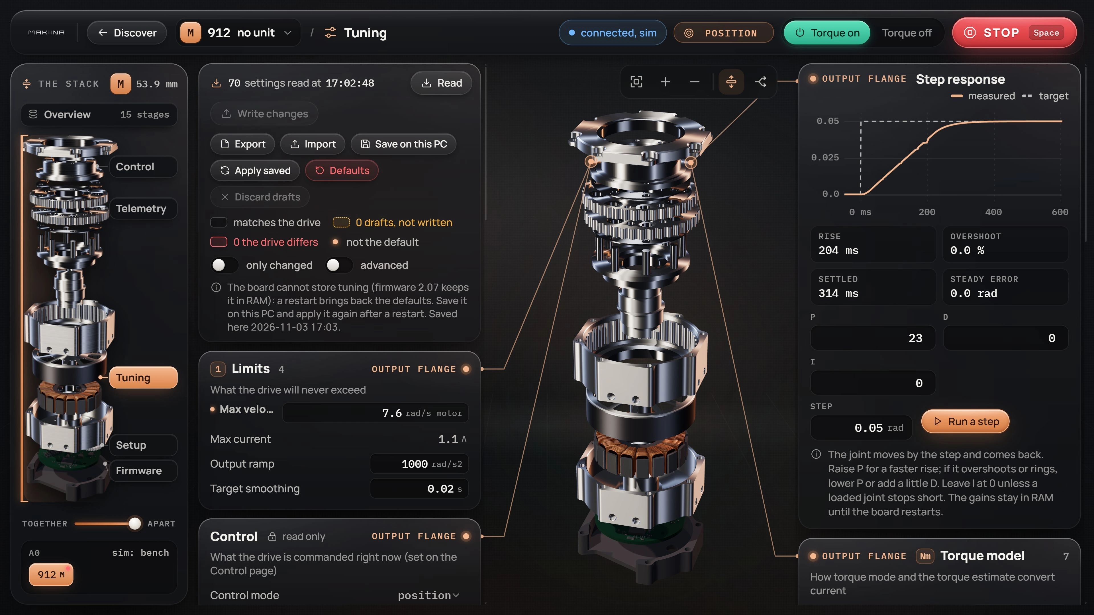
- Read the running values before changing them. Readback needs firmware 2.04 or newer; an unsupported field is not a confirmed value.
- Change one setting, then press Tab to leave the field. It becomes a draft; editing the field has not written it to the drive yet.
- Press Write changes. The Console writes the drafts and reads them back. A mismatch is marked; do not treat it as an accepted setting.
- Make a small test move and compare the response. Keep the original value so you can restore it if the response gets worse.
- Once the response is suitable, press Save on this PC to save the running settings for this board.
Tuning keeps firmware units. A speed labelled rad/s motor is before the gearbox; its help also gives the output value. Control's output speed slider and this motor-speed field must not be given the same number.
Test a position step
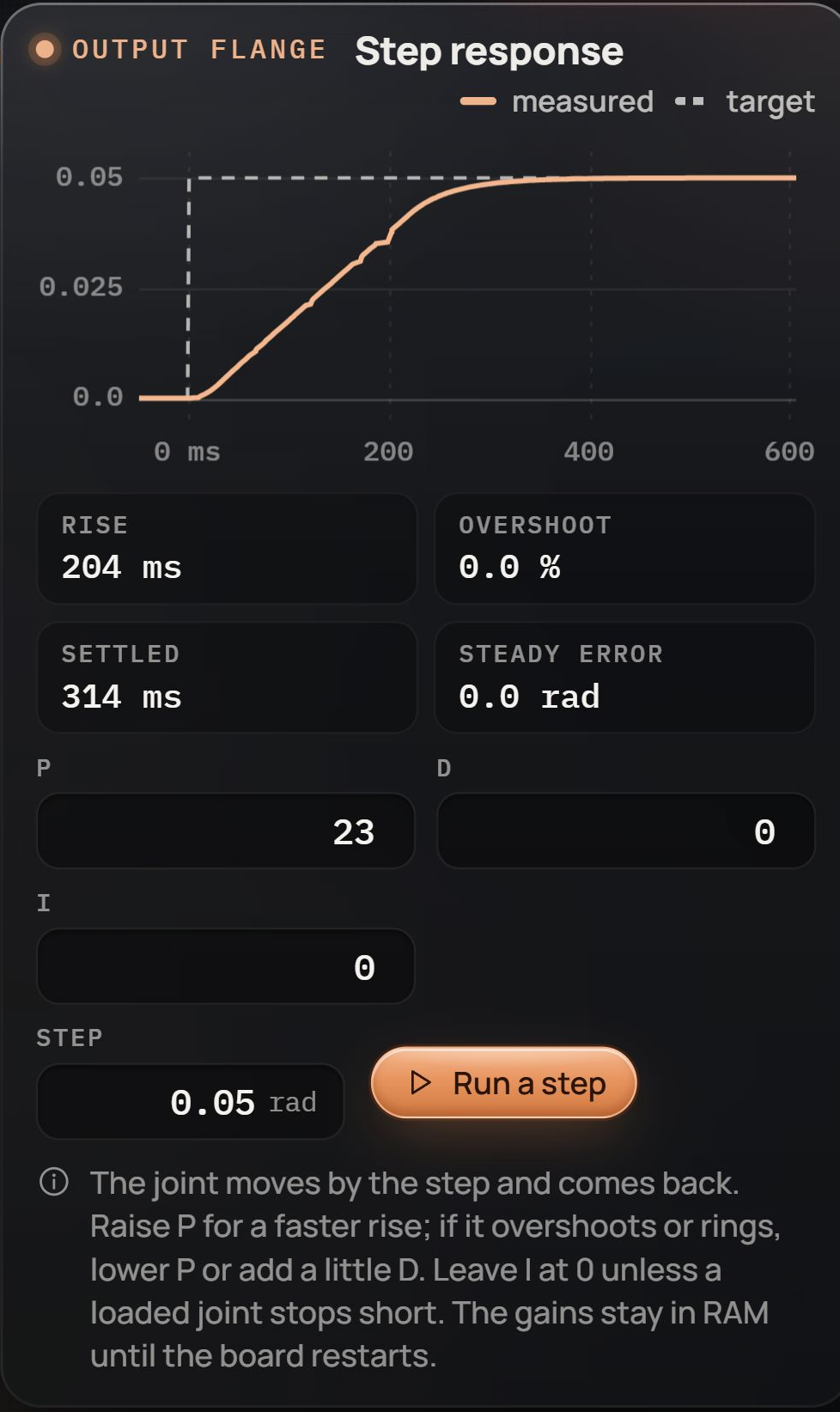
The step-response panel puts the position P, D and I gains beside a small motion test. With the output clear, Torque on and conservative limits, enter a small Step, such as 0.05 rad, then press Write and run a step. With no gain drafts, the button says Run a step. It moves the output by the step and returns; with gain drafts it writes them first.
Compare the measured curve with the target. Rise time describes how quickly it approaches the target; overshoot shows how far it goes beyond it; settling time describes when it stays near it. The steady error is the remaining difference. Increase P gradually for a quicker response; if it rings or overshoots, reduce P or try a small increase in D. Leave I at zero for the first unloaded test.
Keep a tuning for the next session
| Action | What it changes | What to do next |
|---|---|---|
| Edit a field | A draft in this page | Press Write changes to apply it. |
| Write changes | The drive's running settings | Check the readback, then test. |
| Save on this PC | A profile for this board on this PC | Use Apply saved after a board restart. |
| Apply saved | Writes that profile to the selected board | Check readback and limits before moving. |
| Export | Downloads a JSON settings file | Keep it as a backup or copy it to another PC. |
| Import | Writes the selected file to the drive after confirmation | Check the board, size and values before confirming. |
| Defaults | Writes firmware defaults | Review limits before enabling motion again. |
The current Console treats tuning as temporary on the board: a restart returns it to firmware defaults. A saved profile is not applied automatically. Profiles live in ~/.makiina/actuator-console/profiles/, identified by the board's chip ID. Export a copy when moving to another PC.
Save after writing your drafts: saving the running settings does not apply an unwritten draft. Profiles are drive settings, not complete Console sessions; do not expect them to restore a waveform, waypoints or every Console control. Check the Control limits again after applying one. Zero, direction and identity have separate permanent storage on Setup.
Read and record telemetry
Open Telemetry for the selected actuator. The live channels are attached to the parts they describe: output position and error, motor current and temperature, and the driver state.
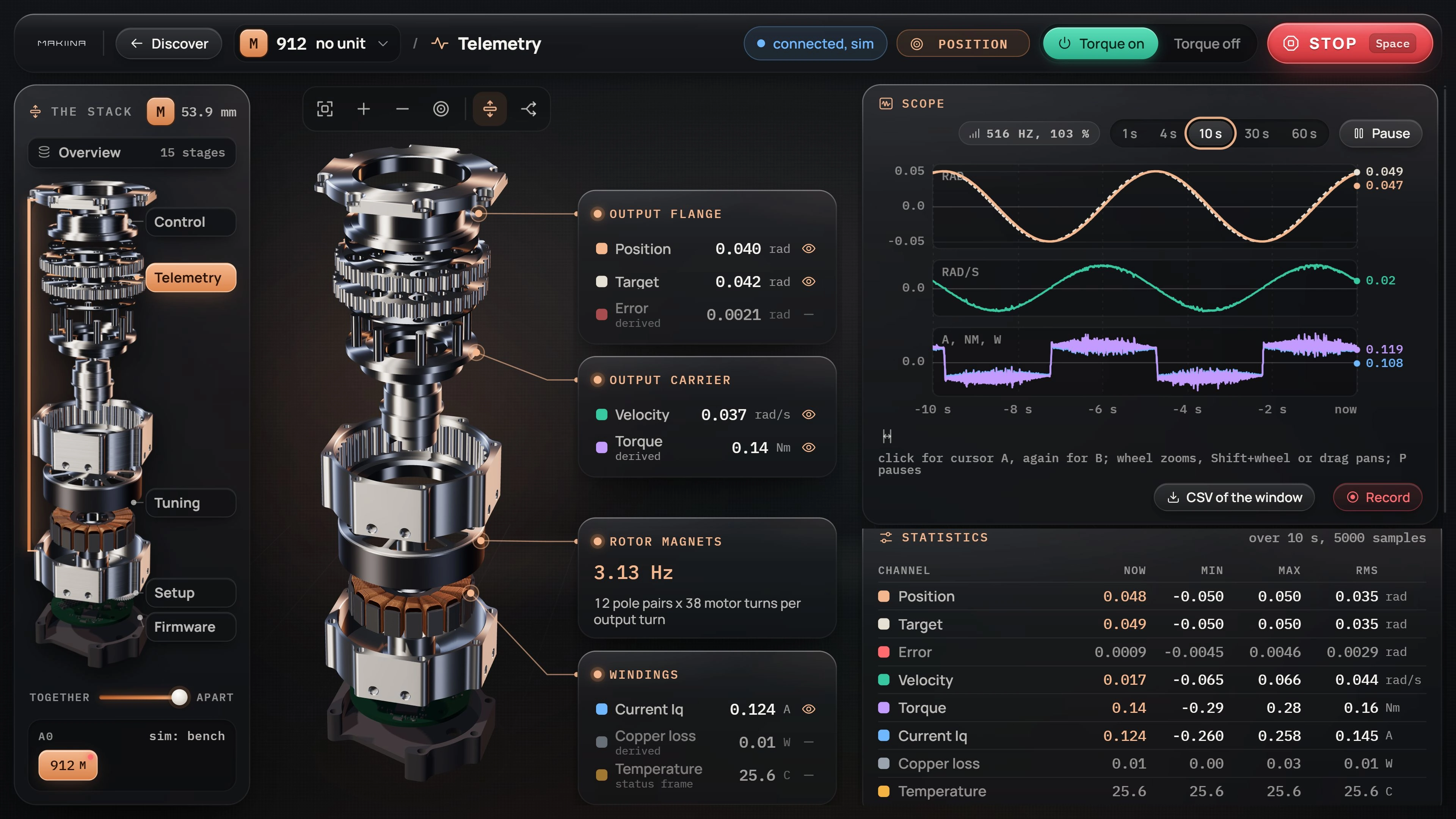
- Click the channel rows to show or hide curves. Start with position, target and error; add current to see the effort during a move.
- Choose a window, such as 4 s or 10 s. The chart shows that length of recent history.
- Make a small move from Control, then return here. Click the chart for cursors and use the wheel to zoom into the response.
- Press Pause to inspect a fixed view. This freezes the chart, not the actuator. Use STOP to stop motion.
- Press CSV of the window to download the samples in the selected time window. Resume returns to the live chart.
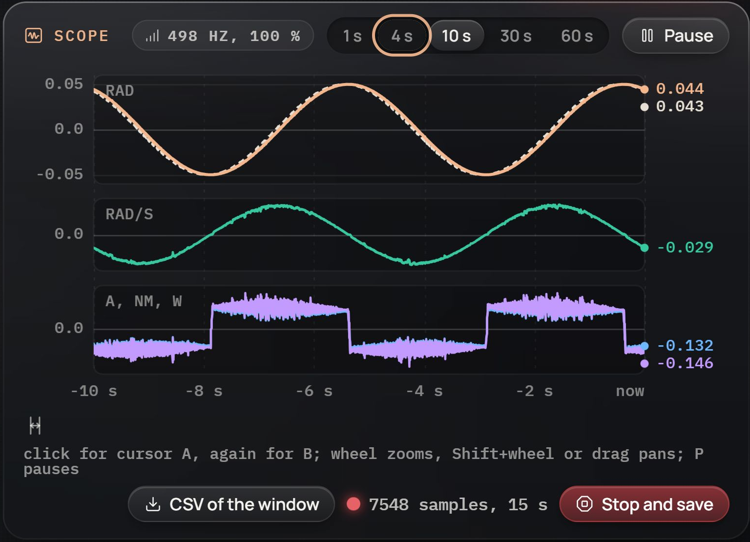
For a longer capture, press Record, keep the Telemetry page open while the signal you want occurs, then press Stop and save. The browser downloads the recorded samples as CSV. Stopping the recording does not stop motion. For a repeated motion, start a small waveform on Control first, then record it here; finish with STOP.
The displayed rate and delivery percentage help you judge the capture. The current spectrum shows periodic components of motor current; it is useful when a repeated motion or vibration leaves a regular pattern. Temperature on older firmware is polled more slowly than motion state.
Understand stops and warnings
| Action or event | Result |
|---|---|
| Top-bar STOP, STOP ALL, or Space outside an input | End motion and hold every drive this Console enabled. |
| Stop beside the selected board ID | Hold that actuator only. |
| Release a Jog control | Stop the jog; a lost release expires in 0.4 s. |
| Torque off | Confirm, then gradually release current. Support a load first. |
| Browser closes or goes silent | The running server's default watchdog holds enabled drives. |
| Console process crashes or PC sleeps | The browser watchdog cannot act; a drive may continue its last command. |
Firmware 2.06 and later reports a thermal guard. At its normal 85 °C trip limit, drive current ramps down. The Console stops other enabled motion when it sees the trip. A cooled drive can be revived below 75 °C; the Console normally does this automatically, holding the current position and ramping current back in. After three automatic revives within an hour, another trip needs Revive manually. Investigate repeated trips and reduce the load; do not treat a cooled drive as permanently released.
If a command is refused, read the warning before retrying. For missing boards, size questions and update recovery, use Actuator maintenance.
Continue by task
- Drive an actuator from PythonUse the same board ID and adapter after closing the Console.
- Update or configure an actuatorFollow the illustrated firmware and Setup steps.
- Console launch optionsChoose adapters, simulation, a port or a profile folder.
- Actuator API referenceLook up the Python properties, units and supported operations.