
Set up your systemActuatorSet up the actuator
Set up an actuator
Connect an actuator to your PC, open the Actuator Console and check that its live readings arrive.
At the end of this page the Actuator Console shows your actuator and its live readings. It runs on your PC through a USB CAN adapter. Your MAKIINA account is for downloading the SDK kit; operating the actuator needs no sign in or network connection.
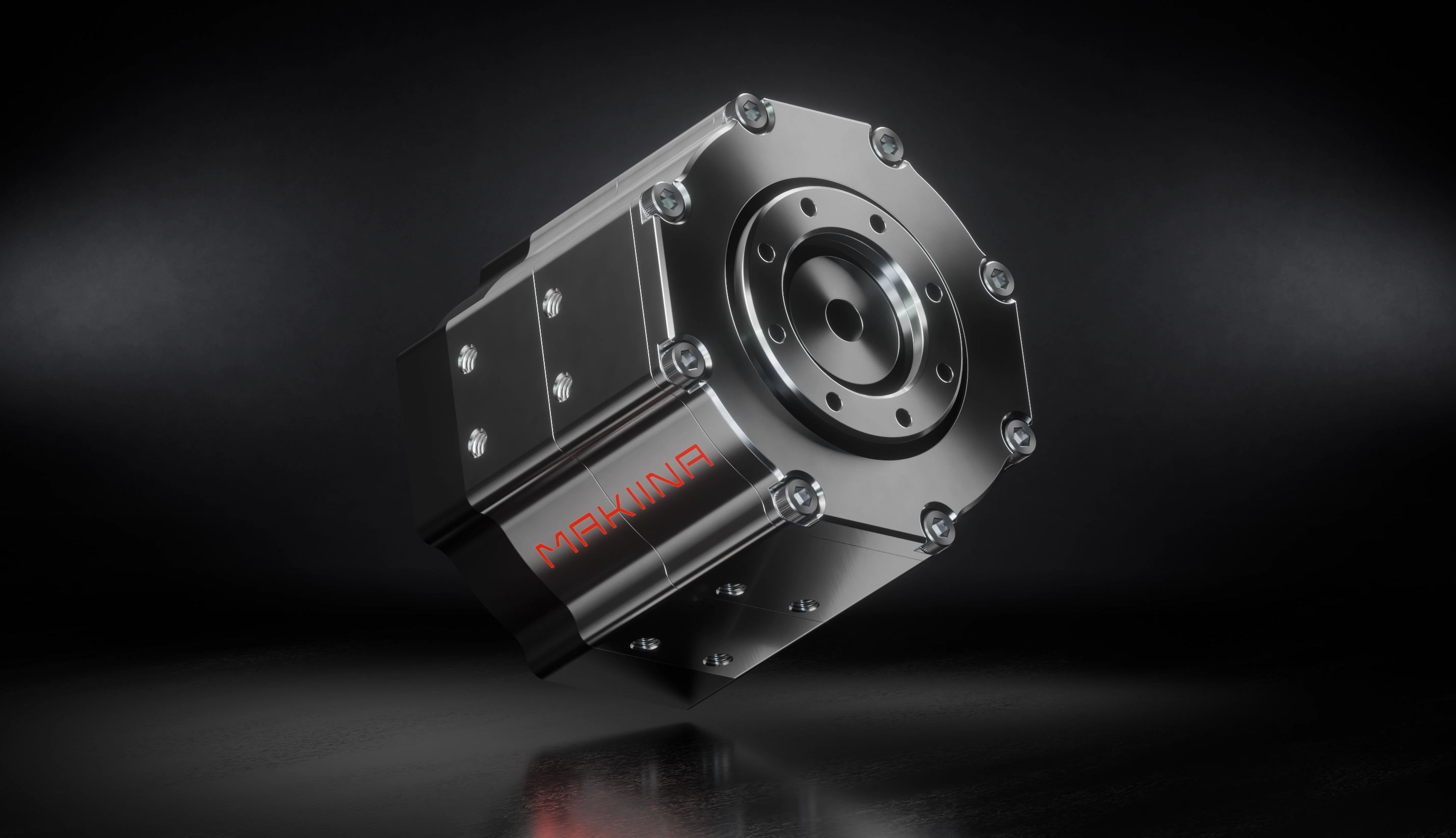
For a complete arm, follow Set up the arm kit. Its Robot Console controls the joints together. This path is for an individual actuator, or actuators in a machine you are building.
Have these ready
- Your actuator, secured to a bench or fixture, with its output free to turn.
- A 24 V DC supply with a current limit and a switch you can reach. USB powers the CAN adapter, not the actuator. Match the supply and cables to your actuator and load; the motor current shown in the Console is not the same as current drawn from the supply.
- A candleLight USB CAN adapter and the power and CAN cables for your actuator. Check your order for which cables and adapter are included.
- CAN termination at both ends of the bus: the adapter end and the last actuator. The actuator controller board already contains its 120 ohm resistor; enable it through software, without adding an external resistor. See Set the actuator bus termination for the adapter end and which actuator to enable in a chain.
- A Windows or Linux PC and the SDK kit for it (supported systems).
Install the SDK kit
- Sign in at
cloud.makiina.com/account. Create an account if you have none. A standalone actuator has no robot to claim, so skip Add a robot. - Open SDK, press GET DOWNLOAD LINK for your PC, then DOWNLOAD NOW. Unzip the kit into a new folder.
- Run the kit's setup as in Install the SDK. Keep the whole folder together; the launchers use the
.venvit creates. - On Windows, give the adapter its driver. On Linux, follow the CAN interface setup.
Connect power and CAN
- Keep the 24 V supply switched off while connecting cables. Secure the actuator body and keep fingers, tools and loose cables clear of its output.
- Connect the adapter to the actuator's CAN cable, then to a USB port of your PC. Follow the connector labels for CAN H, CAN L and ground; the diagram shows the connections, not a connector pinout.
- Check termination at the adapter and the last actuator. For one actuator, that actuator is the last one. Its resistor is built into the controller board and enabled in software, after power is on. Follow Set the actuator bus termination for the software switch; no extra resistor is needed at the actuator.
- Connect the actuator's power cable to the supply with the correct polarity, then switch it on. A powered drive can hold its position before the Console takes control.
- Close any script, notebook session or Robot Console tool using this adapter. The Actuator Console holds it until the Console exits.
Open the Actuator Console
On Windows, double-click ActuatorConsole.bat in the kit folder. From PowerShell in that folder, use:
.\ActuatorConsole.batOn Linux, with can0 set up at 1 Mbit/s:
./actuator_console.shFor the USB path on Linux instead of can0, use ./actuator_console.sh --interface candle after the USB permissions setup in Install the SDK.
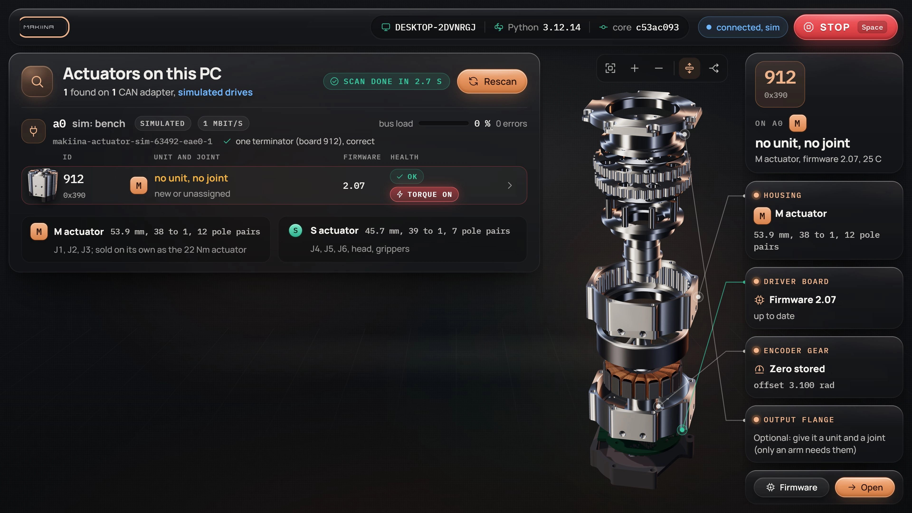
The browser opens http://127.0.0.1:8727. Discover lists the adapters and the actuators that answered. Rescan checks again after you connect or power a board.
Check which actuator you found
Read the board's ID, size and firmware on its row. The ID is the drive's address on this bus, shown in decimal and hexadecimal, for example 912 and 0x390. It is not a joint number.
Open the row, then choose Overview in the left navigation. Check that the model matches the physical actuator and that its position and temperature arrive. A standalone actuator does not need a unit or joint assignment.
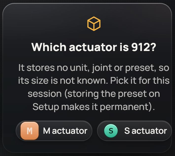
If the size is ?, select M or S only after checking the hardware. This selection is for this Console session; storing a motor preset is a separate maintenance step. Until the size is known, readings use motor units, marked rad motor.
Try it without hardware
Start a separate simulated session from the kit folder:
.\ActuatorConsole.bat --sim 1./actuator_console.sh --sim 1The page says connected, sim. This example starts with an unconfigured M actuator, so its firmware and setup warnings are expected. You can try those tools without changing hardware. Close the simulated Console before starting the hardware session.
If the actuator does not appear
| What you see | What to do |
|---|---|
| No adapter | Check USB and the Windows driver or Linux interface setup, then press Rescan. |
| Adapter, but no actuator | Check the 24 V supply, CAN cable and actuator bus termination, then Rescan. |
| Adapter is in use | Close the program holding it, including notebook kernels with an open drive. |
| Cannot open device after a crash | Close the Console normally, wait about two minutes or re-plug the adapter, then start again. |
| Two boards share an ID | Follow Resolve an actuator ID collision. |
| Board in bootloader | Follow Update actuator firmware. |
Once Overview shows the right actuator and live readings, continue to First move.